Visual overview
From cross section to shear stress
Start with the question
Which formula do you need?
If you already know J, skip the geometry step. Otherwise, calculate it once and carry it into both stress and twist.
What is the section property?
Start here when you have the shaft dimensions. J describes the circular cross section and feeds both calculations that follow.
You need: Outer and inner radii; set the inner radius to zero for a solid shaft.
Open formula & calculatorHow large is the shear stress?
Use the internal torque at the section and the radius of the point you want to check. The outer surface gives the maximum stress in this model.
You need: Internal torque T, polar area moment J, and evaluation radius r.
Open formula & calculatorHow much does the shaft twist?
Use this to find the relative rotation between the ends of a uniform segment. Stress and twist are different checks: a low-stress shaft can still rotate too much.
You need: Internal torque T, length L, polar area moment J, and shear modulus G.
Open formula & calculatorCheck the model first
Before you start: Torque, basic algebra, and consistent units.
- Solid or concentric hollow circular shafts, away from load application points and local stress concentrations.
- Homogeneous, linearly elastic material with small strains under static or slowly applied loads.
- The single-segment twist equation assumes constant internal torque, cross section, and shear modulus along the length.
Put it together
One shaft. Three connected steps.
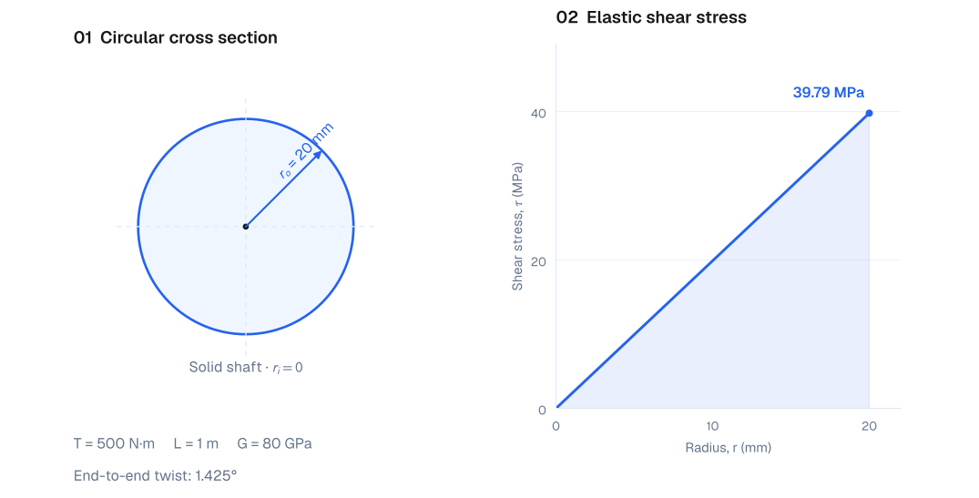
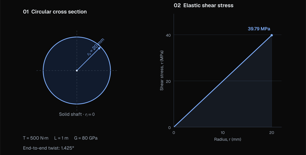
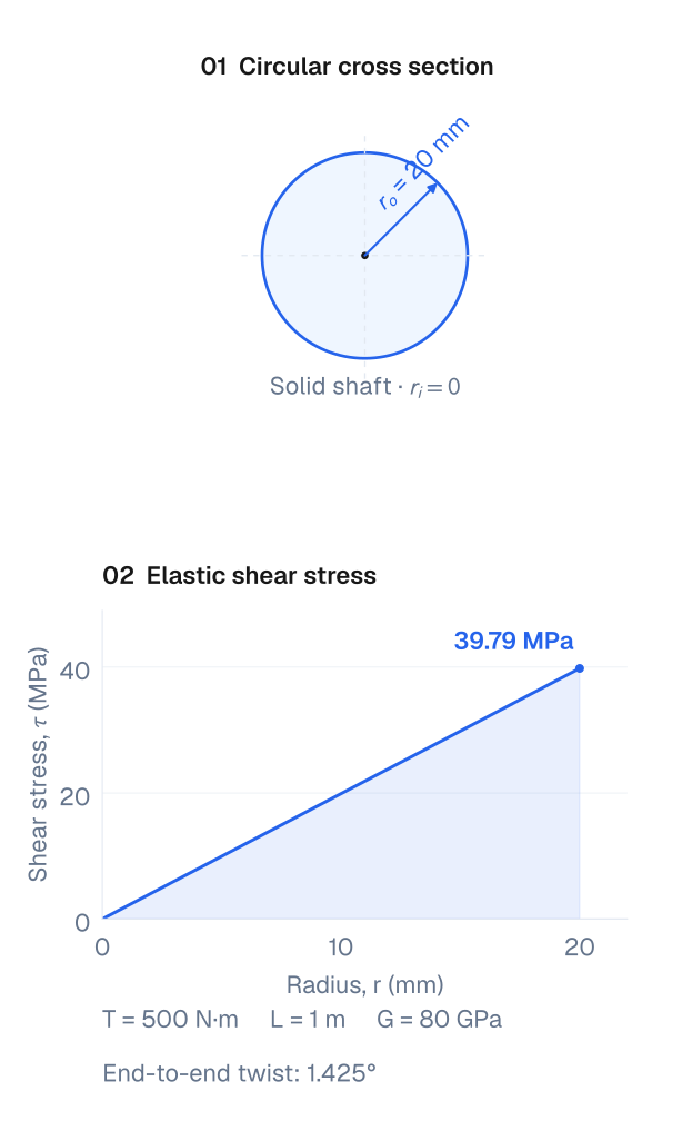
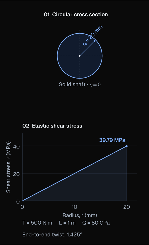
A uniform solid shaft is 40 mm in diameter and 1 m long. It carries a constant internal torque of 500 N·m and has a shear modulus of 80 GPa. Find its maximum shear stress and end-to-end twist.
01Turn the geometry into J
Convert diameter to radius: 40 mm ÷ 2 = 20 mm = 0.020 m. The solid section has no inner hole.
Try your own values02Check the outer-surface stress
Use r = rₒ for the maximum stress. Carry the unrounded J into the next calculation, then convert pascals to megapascals.
Try your own values03Check the end-to-end rotation
Use the same J and torque, together with the segment length and shear modulus. The result is in radians; multiply by 180/π to get degrees.
Try your own values
The shaft develops about 39.79 MPa of maximum shear stress and twists by 0.02487 rad (1.425°). Compare these separately with the stated allowable shear stress and twist limit; these results alone do not establish that the shaft is acceptable.
Small mistakes that change the answer
Putting a diameter into a radius equation
The displayed J equation uses radii to the fourth power. Using diameters in it makes J sixteen times too large. In diameter form, use J = π(dₒ⁴ − dᵢ⁴)/32.
Mixing geometric J with mass inertia
The J here has units of m⁴. A rotational mass moment in kg·m² describes a different property and cannot be substituted.
Losing the unit conversion
Convert all lengths consistently before calculating J. A result in mm⁴ converts to m⁴ with a factor of 10⁻¹². Also, 80 GPa is 80 × 10⁹ Pa, and the twist equation returns radians.
Using an applied torque everywhere
Cut the shaft and use equilibrium to find the internal torque in each region. Intermediate gears or pulleys can change it; restrained shafts may also require compatibility.
What if the shaft has several segments?
Split it wherever torque, geometry, or material changes. Find each segment’s internal torque from equilibrium and add the signed twists. Each segment needs its own stress check.
Keep one sign convention throughout. Noncircular sections, plastic deformation, and local notches need a more suitable model.
Check your understandingIf you double the radius of a solid shaft, keeping torque, length, and material the same, what happens to maximum stress and twist?
J increases by 2⁴ = 16. The surface radius also doubles, so maximum stress becomes 2/16 = 1/8 of its original value. Twist becomes 1/16 of its original value. This comparison holds within the same elastic circular-shaft model.